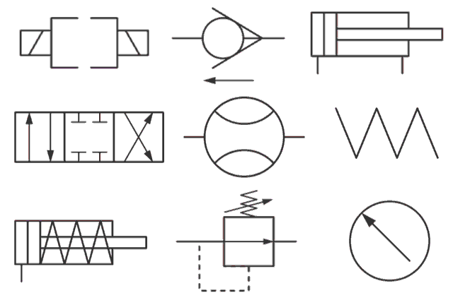
Imagine trying to navigate a complex city without street signs. Confusing, right? Hydraulic systems, the powerhouses behind countless machines, operate similarly. Without a standardized language of symbols, deciphering their intricate workings would be a chaotic endeavor. That's where the crucial role of common hydraulic symbols comes into play. These visual cues represent various components, connections, and functions within a hydraulic system, providing a universally understood roadmap for engineers, technicians, and operators.
Hydraulic symbol interpretation forms the foundation for effective design, maintenance, and troubleshooting of hydraulic systems. From simple pumps and valves to complex circuits, these symbols communicate vital information about the flow of hydraulic fluid and the operation of individual components. By understanding these symbolic representations, professionals can efficiently analyze system performance, identify potential problems, and ensure safe and reliable operation.
The history of standardized hydraulic symbols is tied to the increasing complexity of hydraulic systems. As these systems became more sophisticated, the need for a universal visual language became evident. Organizations like the International Organization for Standardization (ISO) played a vital role in developing and promoting the use of consistent symbolic representation. This standardization has significantly improved communication and collaboration across the industry, reducing ambiguity and errors in system design and maintenance.
One of the primary challenges related to hydraulic symbols is ensuring consistent application and interpretation across different industries and regions. While ISO standards provide a valuable framework, variations and regional adaptations can sometimes lead to confusion. Therefore, ongoing training and adherence to updated standards are essential for professionals working with hydraulic systems. Staying abreast of the latest developments in symbolic representation is critical for accurate communication and effective system management.
Understanding basic hydraulic symbols is akin to learning the alphabet of fluid power. For instance, a circle represents a pump, while a square with an arrow indicates a directional control valve. Lines connecting these symbols depict the flow of hydraulic fluid, allowing engineers to visualize the circuit's operation. These symbols are not arbitrary; they are carefully designed to convey specific information about the function and characteristics of each component, enabling professionals to "read" and interpret hydraulic schematics with ease.
Three key benefits of using standard hydraulic symbols are clarity, efficiency, and safety. First, the use of symbols provides a clear and concise way to communicate complex information about hydraulic systems, eliminating potential misinterpretations caused by language barriers or technical jargon. Second, these symbols facilitate efficient troubleshooting and maintenance by enabling technicians to quickly identify and isolate faulty components within a system. Lastly, standardized symbols contribute to enhanced safety by providing a universally understood representation of potential hazards and control measures within the hydraulic circuit.
A practical example is a hydraulic press used in manufacturing. The schematic, using standard symbols, will clearly show the pump, valves, actuators, and connections, enabling a technician to understand the flow of hydraulic fluid and diagnose any issues effectively.
Advantages and Disadvantages of Standardized Hydraulic Symbols
| Advantages | Disadvantages |
|---|---|
| Clear communication | Potential for misinterpretation if not adhering to standards |
| Efficient troubleshooting | Requires training and familiarity with the symbols |
| Enhanced safety | Variations and regional adaptations can create confusion |
Best practices for implementing common hydraulic symbols include adhering to ISO standards, providing clear legends on diagrams, using consistent symbol sizes and orientations, regularly updating symbol libraries, and ensuring that all personnel working with hydraulic systems receive adequate training in symbol interpretation.
Frequently Asked Questions:
1. What is the symbol for a hydraulic pump? - Generally represented by a circle.
2. What does a directional control valve symbol look like? - A square with an arrow indicating flow direction.
3. Where can I find a comprehensive list of hydraulic symbols? - ISO standards and online resources provide detailed information.
4. Why is it important to use standardized symbols? - For clear communication and efficient troubleshooting.
5. How can I learn more about hydraulic symbols? - Various online courses, textbooks, and training programs are available.
6. Are there software tools for creating hydraulic diagrams? - Yes, several CAD software packages specialize in hydraulic system design.
7. What are some common mistakes in using hydraulic symbols? - Inconsistency in application and misinterpreting regional variations.
8. What is the role of ISO in standardizing hydraulic symbols? - ISO develops and maintains international standards for hydraulic symbols.
In conclusion, understanding common hydraulic symbols and their meanings is paramount for anyone working with hydraulic systems. From design and maintenance to troubleshooting and safety, these symbols provide a crucial communication tool that ensures efficient and reliable operation. By mastering this symbolic language, professionals can navigate the complexities of hydraulic circuits, enhance system performance, and contribute to a safer working environment. Investing time in learning and applying standardized hydraulic symbols is an investment in effective communication, optimized performance, and enhanced safety within the realm of fluid power technology. Embrace the power of symbols and unlock the full potential of your hydraulic systems.
Unlocking the secrets of the sky your guide to celestial knowledge
Staying informed your guide to watertown ny news
Maximize your miles ram 1500 towing fuel efficiency


